PRODUCT PROPERTIES


PRODUCT RANGE
Length (mm)2500-69992500-69992500-69992500-69992500-6999
| Width (mm) | 1000 | 1250 | 1500 | 1575 | 1750 |
|---|---|---|---|---|---|
| Length (mm) | 2000-6800 | 2000-6800 | 2000-6800 | 2000-6800 | 2000-6800 |
| Solid Colours |  |
|
|
|
 |
| Metallic Colours | |
|
|
|
|
| ALUCOBOND® Spectra & Sparkling | |
|
|
|
— |
| ALUCOBOND® naturAL | — | |
|
— | — |
| ALUCOBOND® Legno – Premium Wood | |
|
|
— | — |
| ALUCOBOND® Anodized Look | |
|
|
|
— |
| ALUCOBOND® Design | |
|
|
— | — |
| ALUCOBOND® Anodized* | — | |
|
— | — |
Footnotes:
on request
TECHNICAL DATA
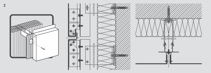
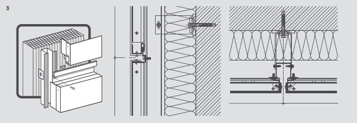
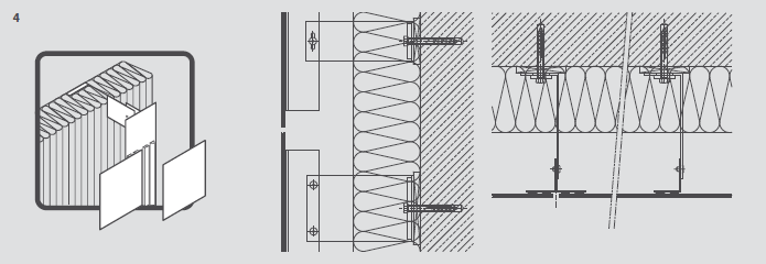
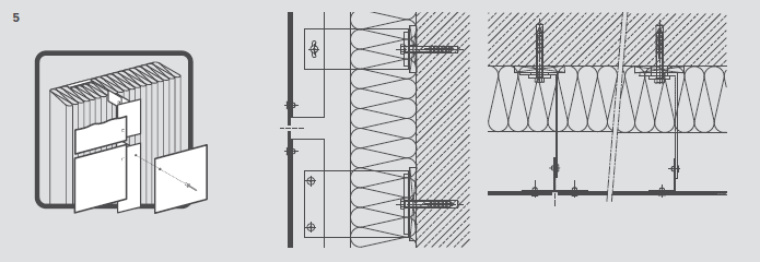
FIXING SYSTEMS
FIRE CLASSIFICATION
INSTALLATION | MAINTENANCE | STORAGE | HANDLING GUIDELINE


ALUCOBOND®
Download our Alucobond processing manualPROCESSING
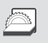


ALUCOBOND® can be cut with a vertical panel saw, circular saw, or jigsaw.
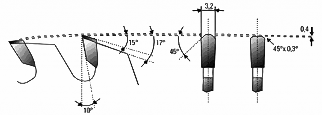
Carbide tipped (CT) saw blades.
Carbide tipped (CT) saw blades for HOLZ-HER and Striebig circular panel saws. Trapezoid/flat tooth saw blade, flat teeth 45° chamfered for burr-free edges.
| Blade geometry | Tooth thickness approx. 2 - 4 mm, tapered to the inside to prevent jamming |
| Tooth geometry | Trapezoid tooth / flat tooth |
| Pitch t | 10 - 12 mm |
| Clearance angle α | 15° |
| Rake angle γ | 10° positive |
| Maximum cutting speed v | 5000 m/min |
| Maximum feed s | 30 m/min |
| Saw blade-Ø | D = 300 mm (for Striebig vertical panel saw Standard II) |
| Number of teeth | t = 72 (for cuts of up to 5 panels) LEUCO Code No. 181724 t = 96 (for single cuts without burrs) LEUCO Code No. 181725 |
| Saw blade-Ø | D = 250 mm (for Holz-Her vertical panel saw 1255 ALUCOBOND®) |
| Number of teeth | t = 60 (for cuts of up to 5 panels) LEUCO Code No. 181726 t = 80 (for single cuts without burrs) LEUCO Code No. 181727 |
| Bore ø | D = 30 mm |
| Tooth thickness | 3.2 mm |
| Clearance angle α | 15° |
| Rake angle γ | 10 ° positive |
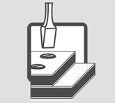
ALUCOBOND® panels of any thickness can be punched using conventional sheet punching machines.
- For clean cuts use sharp tools and dies with minimal cutting clearance (0.1mm). Punching will cause a slight deflection at the cut edge of the impact side.
- Holes having a minimum diameter of 4mm can be punched.
- Distance between the adjacent hole edges should not be less than 4mm.
- Please ask for detailed information on how to perforate ALUCOBOND® before proceeding.
ALUCOBOND® can be cut to shape using jigsaws, a CNC machine, and a waterjet machine.
- While using a jigsaw, use saw blades that are used for cutting wood and plastic material.
- Cut abrasively while using a waterjet cutting machine. Predrilling of panels is required before commencing.
- While using a waterjet, a cut is needed in the middle of the panel as it is not possible to drill through using a waterjet.
- CNC machining centres should use a one edge cutter.
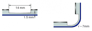
ALUCOBOND® can be bended using a bending press.
- The minimum required radius is r = 10 x t (t = panel thickness).
- The spring-back effect of ALUCOBOND® is greater than that of a solid aluminium sheet.
- The die edges should be rounded and smooth.
- To prevent damage to the panel surface, protective foil must not be removed during bending.
- Additionally, the visible surface can be protected by using plastic pads of 1-2mm thickness
- Ideal die width: 2 x t + 2 x protective foil thickness + punch diameter + 15mm
- Before scaled-up production, testing on the sample panels is recommended.
A = punch
B = protective foil
C = die
D = die width
r = radius
- ALUCOBOND® can be bent using a roll bending machine (3 or 4 rollers). Make sure that the feeder does not exert too much pressure. Bending rollers which are also used for bending other metals must be thoroughly cleaned from swarf before processing ALUCOBOND®. Make sure to use only polished rollers free of dents and other defects.
- To prevent damage caused to the panel surface, the protective peel-off foil must not be removed during bending. Additionally, the visible surface can be protected by using plastic pads of 1–2mm thickness.
- Before scaled-up production, testing on the sample panels is recommended.
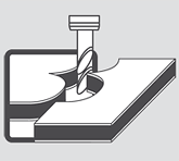
ALUCOBOND® composite panels can be shaped using a very simple processing method. The technique –called the routing and folding method – enables a fabricator to produce shapes of various kinds and sizes. A V-shaped or rectangular groove is routed on the reverse side of the ALUCOBOND® composite panel using a disk or end milling cutter. A thin layer of the core material should be left at the base of the groove, i.e. on the inside of the outer cover sheet. The untouched outer cover sheet can now be bent manually, giving an exact and clean folding line which follows the routed groove. The outer radius of the folded edge depends on the shape of the groove and its depth. We recommend that routing should be done using a vertical panel saw equipped with ALUCOBOND® grooving accessories, CNC machines, a portable sheet milling machine or handheld router. Routing and folding can be done on all the standard surface and finishes of ALUCOBOND® composite panels
Important: When folding ALUCOBOND® with an anodised surface, the folded edges are brighter.
Advantages
The convincing advantages of this unique technique are:
- Low investment cost
- Simple fabrication technique
- Folding can be done on site, saving transportation cost
- Low-cost fabrication of shaped components used in fascia and wall cladding, roof edgings, column cladding, flashings, etc.
- Flexibility in creating shapes
- Very economical
- Shapes are not limited by machine capacity
- The fabrication of shaped components using ALUCOBOND® only requires a minimal investment outlay.
- Hand routers and sheet milling machines are inexpensive and can be used either in the workshop or on site.
- The fabrication of shapes in larger quantities is particularly economical using vertical panel saws equipped with ALUCOBOND® grooving accessories.
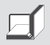
90° V-groove for folds up to 90°
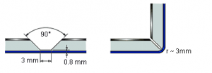
135° V-groove for folds up to 135°
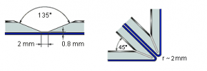
Rectangular groove for folds up to 150°, depending on panel thickness. Not suitable for ALUCOBOND® A2.
Riveting is possible using solid or blind rivets with conventional riveting tools. For exterior applications allow for thermal expansion and use a rivet attachment jig if necessary. ALUCOBOND® panels can be fastened together or joined to other materials using rivets commonly used in aluminium construction. For outdoor use and for use in areas of high humidity, make sure to use aluminium blind rivets with stainless steel mandrels to prevent unpleasant corrosive edges. When using aluminium blind rivets with steel mandrels, the mandrel should drop out after riveting (detachable version). Countersunk rivets are suitable for indoor use only.
For outdoor use please note:
- Use aluminium blind rivets that have been approved for construction with a 5mm shaft diameter and an attachment head diameter of 11mm or 14mm.
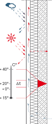
- Please take the thermal expansion of the panel into account (2.4 mm/m/100°C). To avoid jamming, the hole in the panel must be large enough to allow for expansion.
- With the shaft of the rivet fitting closely to the edge of the hole, the attachment head must cover 1mm of the area surrounding the hole.
- Multi-step drills or sleeves with corresponding diameters are used for centrically drilling holes into the panel and the substructure for centrically fitting the rivet.
- Rivet attachment jigs are used for fitting blind rivets without jamming, allowing for a tolerance of 0.3mm.
- Make sure to use rivet attachment jigs and rivets from the same manufacturer, as the height of the attachment head according to DIN 7337 may vary.
- The clamping thickness results from the thickness of the material to be riveted plus an additional value of 2mm to ensure that the closing head is perfectly formed. In accordance with this clamping thickness the corresponding shaft length is determined in the tables provided by the rivet manufacturers. (Lmin = 14 mm).
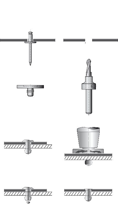
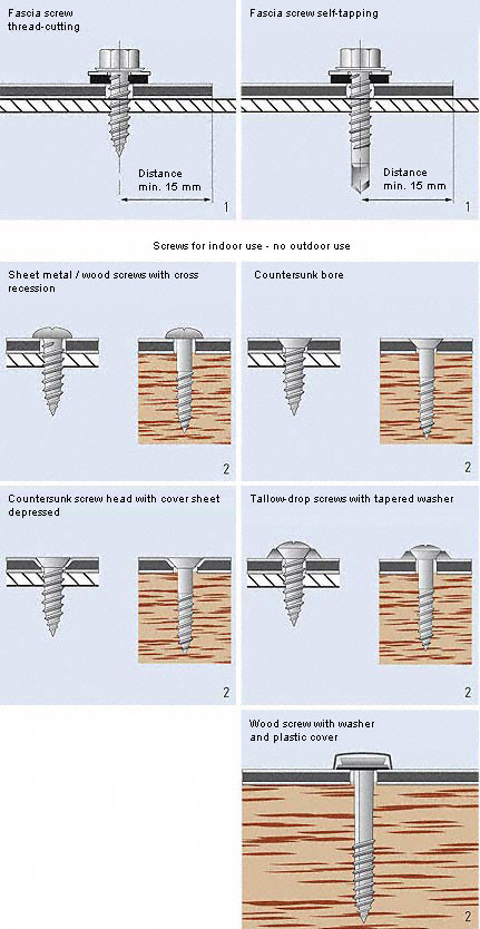
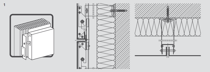
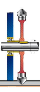
Threaded fasteners for outdoor use
For outdoor use make sure to take the thermal expansion of the panel into account. To avoid jamming, the hole diameter in the
panel must allow for the expansion. Fastening without jamming is possible using fascia screws made of stainless steel with
sealing washer (Fig. 1) that have been approved for construction. The screws must be suitable for the corresponding substructure
(please note the information given by the manufacturer). The screws should be tightened with a torque wrench or screwdriver so that
the sealing washer is placed on the panel for sealing the bore hole without exerting pressure to the panel. Multi-step
drills or sleeves with corresponding diameters are used for centrically drilling holes into the panel and the substructure, and
for centrically fitting the rivet. Important: Make sure to remove the protective foil only from the screwing area prior to screwing.
Threaded fasteners for indoor use
Screws for sheet metal and wood with different head shapes can be used for indoor application (Fig. 2). They do not normally allow for any panel expansion. Countersunk screws can be inserted by the usual countersinking method or by depressing the aluminium surface into the panel. When depressing the aluminium surface, the hole diameter in the panel must be larger than the screw diameter.